| |


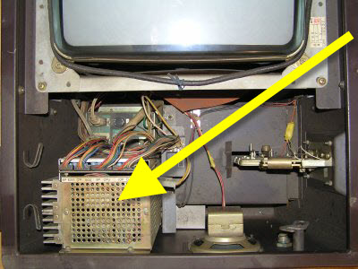 |
PP7A is a switching power supply located in a metal box on the left side of the monitor. This picture shows the cocktail table version of Radar Scope and the arrow points to the PP7A located behind the coin box. |
 |
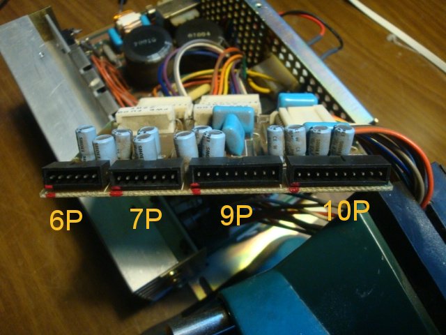
The 6P ESS and 7P SOU plugs are on the back side of the box. Seen from the solder side, you will have the two GND pins of the 6P ESS on the left as in this picture |
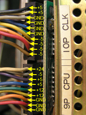 |
On the top of the plug you can check voltages by applying the probe during attract mode.
In a working game they were, for example: 4.83 V (low by 3.4%) / -5.07 V / 12.04 V / 23.33 V |
| +5 Volts | @pin |
| 6P-4 | |
| 6P-5 | |
| 7P-6 | |
| 9P-6 | |
| 9P-7 | |
| 10P-9 | |
| 10P-10 |
| -5 Volts | @pin |
| 6P-6 | |
| 7P-7 | |
| 9P-8 | |
| 10P-1 | |
| 10P-2 | |
| 10P-3 | |
| 10P-4 |
| +12 Volts | @pin |
| 6P-3 | |
| 7P-5 | |
| 9P-4 | |
| 9P-5 |
| +24 Volts | @pin |
| 9P-9 |
| Ground | @pin |
| 7P-1 | |
| 7P-2 | |
| 10P-5 | |
| 10P-6 | |
| 10P-7 | |
| 10P-8 |
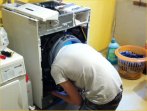
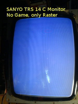
After almost 40 years of service my cocktail table PP-7A power supply failed. The symptom was this:
 |
Suspecting a game boardset failure, i removed the boardset from the machine and tested it on a different monitor. It was working there. So it was a power supply issue. As i measured the voltages at the power supply i noticed that the +5 voltage was missing, but the -5V, the +12V and the +24V were all OK. I took the PP-7A out and took it apart. |
 |
Although one can replace such a power supply with a new one that has the right specs, or even use two
switching power supplies as described below, i think a repair attempt is the right thing to do.
The quality of these parts must have been good, considering mine had a working life of 39 years.
Maybe a new one would not last that long...
You need some electronics know how, though. I suggest you consider Samuel Goldwassers excellent
Notes on
the Troubleshooting and Repair of Small Switchmode Power Supplies
If that document sounds interesting to you, (and all safety reminders apply) read on. The PP-7A schematic is here. You need it, and it is rather easy to understand. Take the metal casing fully apart (some pictures or markings on the sides of the thing are very helpful later). Lots of screws have to be removed, but finally you can spread the two main circuit boards apart. The third one (connector board) is where you can connect a dummy load now. This design would work without load, but a small light bulb is a handy indicator. In the picture on left i have marked each connectors pin 1 with a red dot. On the schematics right hand they are to be found as DC Output numbers (6P- 7P- 9P- 10P-). Now you can take measurements you cannot take if you leave the sandwiched boards inside. In my case, the missing +5 V suggested to check the input and output of TR2. Since the other three voltages are generated on the second circuit board, and they were OK, the main rectified input (measured about 132 V at R1, next to the bridge rectifier BR2, where you can probe safely) could not be the problem. It is shared by both boards. The problem was now a "startup problem" of only one switcher board. The design of the other one is identical. IC1 is the controller for the +5 volts. IC2 for the rest. Both IC are obsolete, so be careful with probing. In my case i checked Pin 6 of IC1 and there was no +12 volts there. It turned out that the internal CONB connector between the boards had a broken solder joint on pin 1 (CONB-1), from where IC1 should get power. So check all connectors first, look for dried out electrolytic caps next and see the troubleshooting paper link above for other tests that might apply to your PP-7A problem. If you have suggestions, please send me an E-mail. |
If you have a defective power supply and you cannot repair it you can replace it by using two switching power supplies, one for the +5 and the +12 volts and another for -5 Volts.
The reason for the necessity of two supplies is that the CLK board with its ECL
logic draws a large current of several amperes at -5V.
The original power supply has the following specs
| +5 V DC | up to 7.5 A |
| -5 V DC | up to 6.5 A |
| +12 V DC | up to 100 mA |
| +24 V DC | up to 200 mA |
The 24 Volts are being used for the game counter and can be omitted if necessary
A very good replacement for the PP7A power supply are two PC power supply units from old PC's. For example, I have used two identical Magnetek power supplies which are too weak for modern PC's (having only 65 W per unit) But they can be used as a Nintendo replacement PP7A without problems
You will have to wire them in the following way:
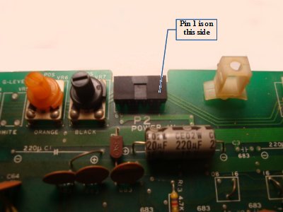 |
This is the edge of a TRS-02-ESS board, showing the P2 POWER IN connector from the component side. PINS 1 and 2 are GND, 3 is +12V, 4 and 5 are +5V, 6 is -5V. See also in the video section. |
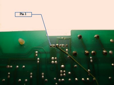 |
Backside of the same board. The jumper cable on the solder side is on PIN 3 (+12V). Note that in the schematics (PDF) of the ESS board the pins are numbered in mirrored fashion (which is an error). |