| |
![]()
![]()
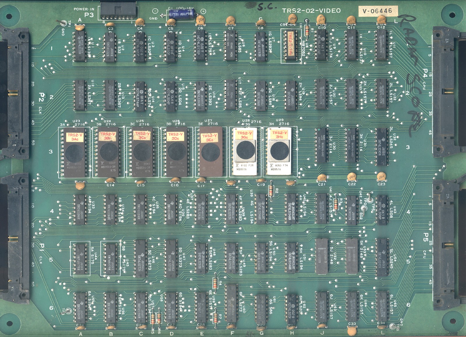 |
Click the picture to enlarge this VIDEO board (TRS2-02-VIDEO version, 638 KB) |
 |
Click the picture to enlarge this ESS board (TRS-02-ESS version, 363 KB) |
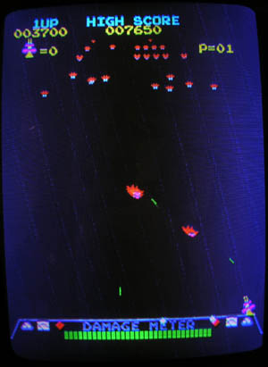
Radar Scope is vertically oriented: Think about an ordinary TV set, where the width is greater than the height. Now let the set stand on its right side. What was the horizontal axis before is now being turned into the vertical. But inside the set the horizontal deflection circuit is the same. Where it traced the beam 'left to right', it now moves it 'top to bottom'. The vertical deflection behaves accordingly.
Radar Scope is just like this TV set turned sideways. What you see as a vertical line on the game actually stretches in the horizontal axis, and what you see as a horizontal line actually is a vertical one.
This may be important to remember as you are troubleshooting something, be it deflection circuits on your monitor or, for example, the line buffers as described on the troubleshooting page.
Since this is a video game system designed in the late 1970's, the CPU, a Z80, has to deal with a lot of processing load. Not only the actual game calculations but also user input servicing has to be done as fast as possible. And how can the CPU control the raster graphic display too?
The answer is a dedicated display hardware that relieves the CPU from its responsibilities for display control.
If you observe Radar Scope during gameplay it is obvious that you have a combination of two picture patterns in a single picture frame:
There is a motion picture pattern with (mostly) moving objects and a still picture pattern which defines the background of the picture frame. Radar Scope has a foreground generator and a background generator.
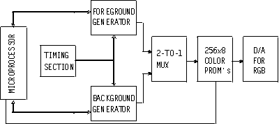 The foreground generator uses two line buffers, each buffer capable of storing
data to represent one horizontal line of the picture. While one buffer outputs
a data stream for controlling the video output stage, the other buffer is being
loaded with data for the following line.
The foreground generator uses two line buffers, each buffer capable of storing
data to represent one horizontal line of the picture. While one buffer outputs
a data stream for controlling the video output stage, the other buffer is being
loaded with data for the following line.
At the output of the active (line displaying) buffer, the data is mixed with the data stream from the background generator. Where there is information for both foreground and background, the foreground simply takes precedence and the background data is not shown.
The CPU, in order to control the display hardware, has a regular schedule to transfer data to it: It is during the vertical blanking interval, which occurs 60 times a second, when the CPU updates the video ram for the foreground.
In order to speed this up, Radar Scope uses a DMA controller. It is the 8257 DMA controller you see on the CPU board next to the Z80: During each VBLK interval the CPU programs the DMA controller with the necessary source and target addresses of the video staging RAM area. This is a 1K RAM area for the foreground. Then the DMA controller takes control of the bus and transfers the current video data directly from program RAM into the video RAMs, without using the Z80. This is a fast transfer of data to the display hardware. Note that the data transferred is not actual "pixel" or "graphics" data, but codes for the type of sprite to use, its horizontal and vertical positions and information if it is to be flipped horizontally or vertically.
After the transfer is over, the CPU takes control of the bus again, services the user inputs and then can continue its game calculations, while the display hardware does the rest. It constantly compares the sprites designated positions with the actual scanning positions and addresses the foreground ROMs which contain the actual pixel data of the foreground objects. The ROMS output the pixel data into a parallel to serial circuit which itself feeds the line buffers mentioned above.
The picture below (which you can download as a pdf file) shows one of the two line buffers. These are located on the CLK board. In the original schematics they are shown on the lower left and right sides of the sheet.
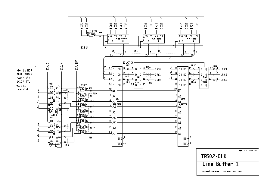
The two RAMs at 5L and 5M are the actual line buffer. For each of the 256 horizontal pixels there are 6 bits of data (V0, V1, C0, C1, C2, C3), where the V are for the video intensity and C for the color bits.
 |
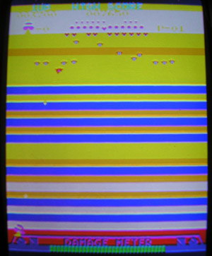
If you remove the 3E Eprom the game will still run but without any grid and stars as in this picture. The blue-to-black-to-blue background is still there. |
 |
Removing the 3G EPROM will create horizontal color bars on the screen as in this picture, while the moving sprites are not affected. Removal of the 3H EPROM looks similar. |
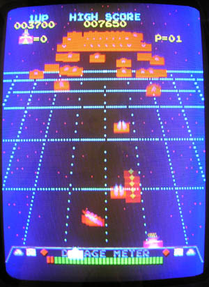 |
The contents of the 3A to 3D EPROMS
are loaded in parallel to a total of eight 4-bit parallel-in 74S194
shift registers. Removing one of them will distort all moving objects,
while the background and grid is unaffected. This picture shows a
disabled 3A EPROM as an example. It seems that the lower half of the
sprites is affected. Since the game screen is oriented vertically, this
means that the horzontal scan lines of the monitor are also in the
vertical axis and in each scan line the same part of sprite data is
left out, resulting in the display of a "block".
Removing one of the other EPROMS (3B, 3C or 3D) results in similar pictures with "red blocks" or "blue blocks" disturbing the "upper" or "lower" half of the sprites. |
 |
Missing color prom 1H on video board. It is the same type (MB 7052) as on the CPU board.
If you have a missing color Prom you can replace it with a GAL as shown on the CPU page. 
|
 |
This is the 6P ESS plug, named [P2] on the TRS 01-ESS board edge
see also in the power supply section for pictures. Note that there is a mirrored numbering in the original PDF schematics. |
 |
Cleaned chassis of a standup Donkey Kong which was originally a Radar Scope. Pictures by SF, Oklahoma
|
 |
The converted TKG above had this original Sanyo Tube 510UTB22 in it.
|
 |
Cleaned neckboard of the tube above.
|